Physical Installation of the Person Reader
Physical Installation of the Person Reader
Overview
The Person Reader is comprised of up to three main sections. These include the Sensor Head, Support Hardware (NUC PC and housing), and the Access Control Panel interface. There are currently five Person Reader sensor heads. All units have a camera system and feedback hardware. Variants include touchscreen and keypad integration and each of these two may optionally include an integrated card reader.
Sensor Head types
- Single gang mounted unit with Camera and A/V feedback - no card reader option
- Single gang mounted keypad equipped unit with Camera and A/V feedback - with or without card reader option
- Double gang mounted touchscreen-equipped unit with Camera and A/V feedback - with or without card reader option.
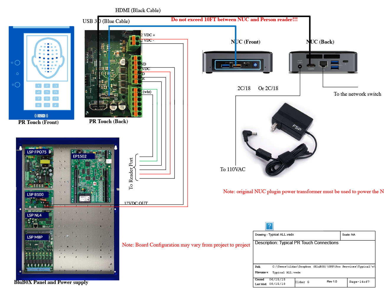
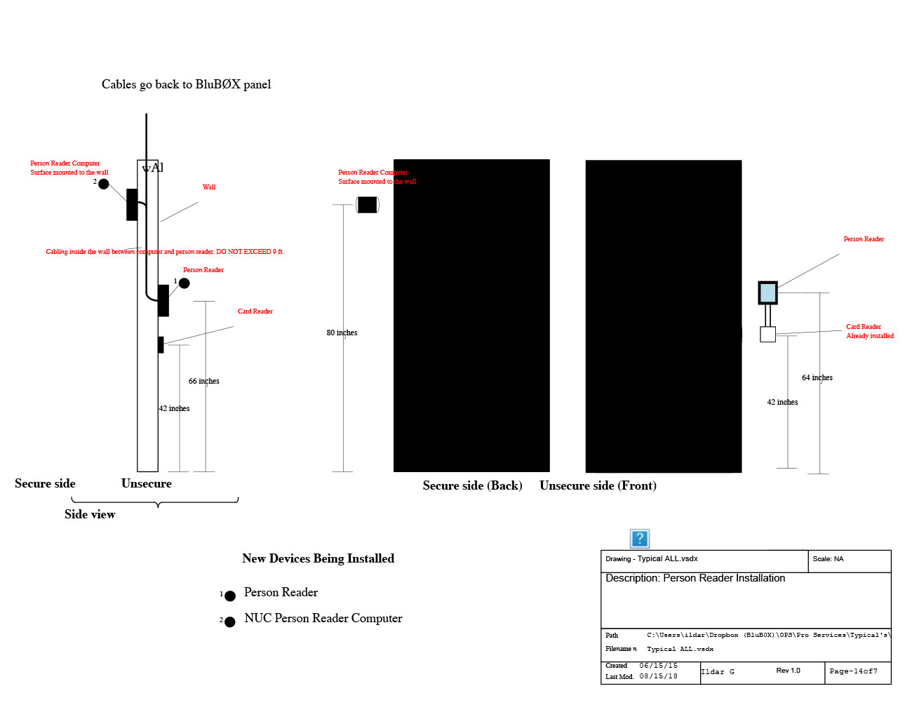
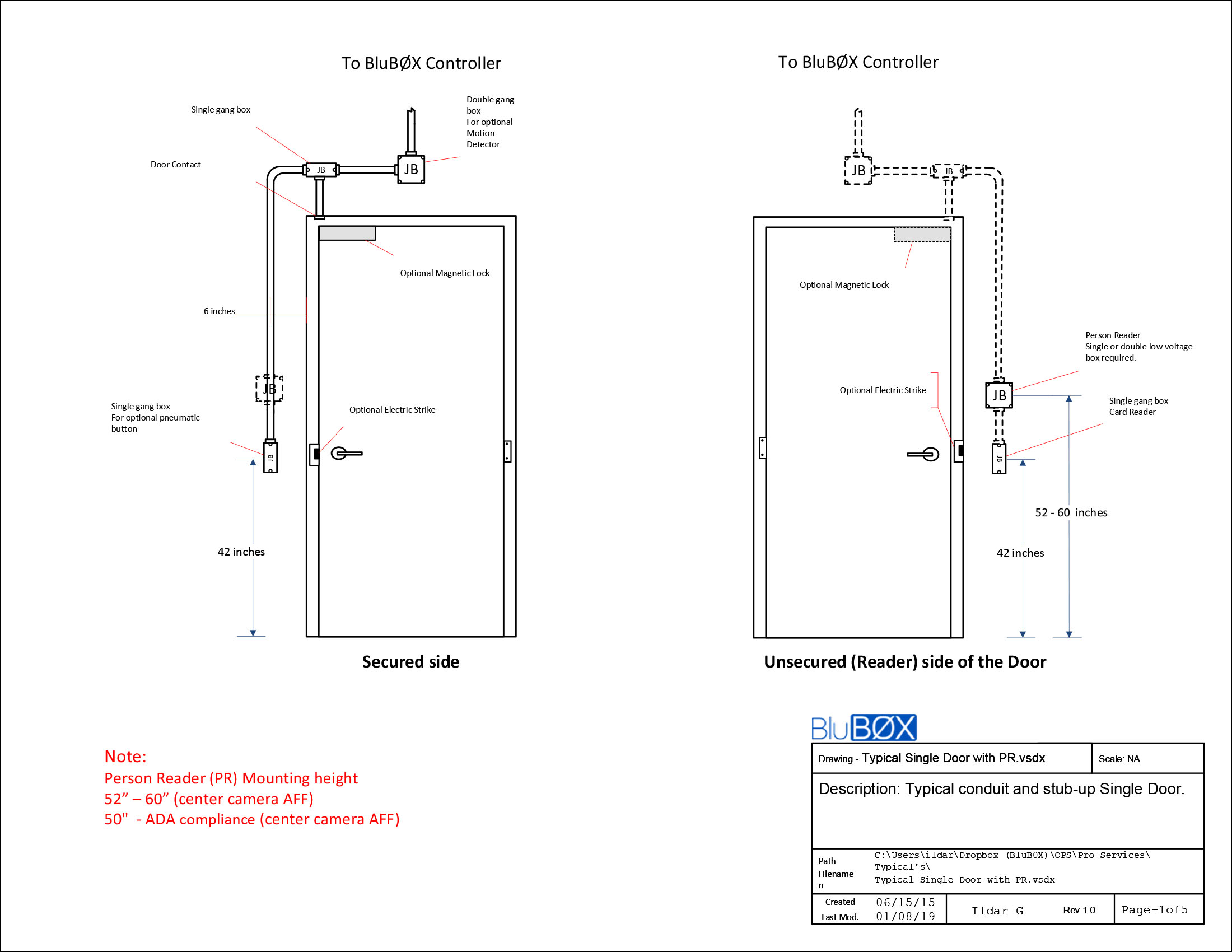
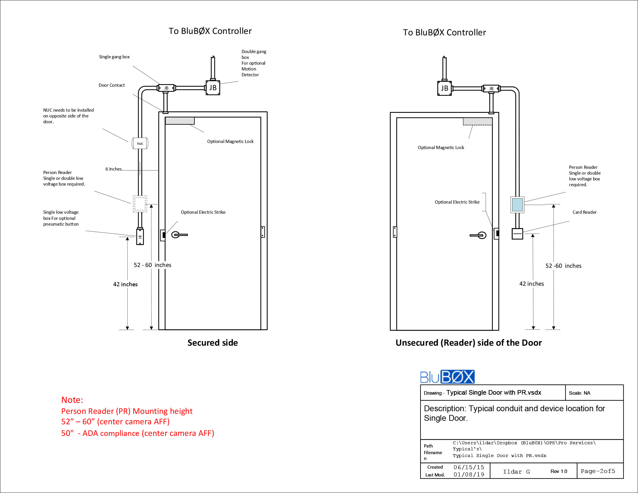
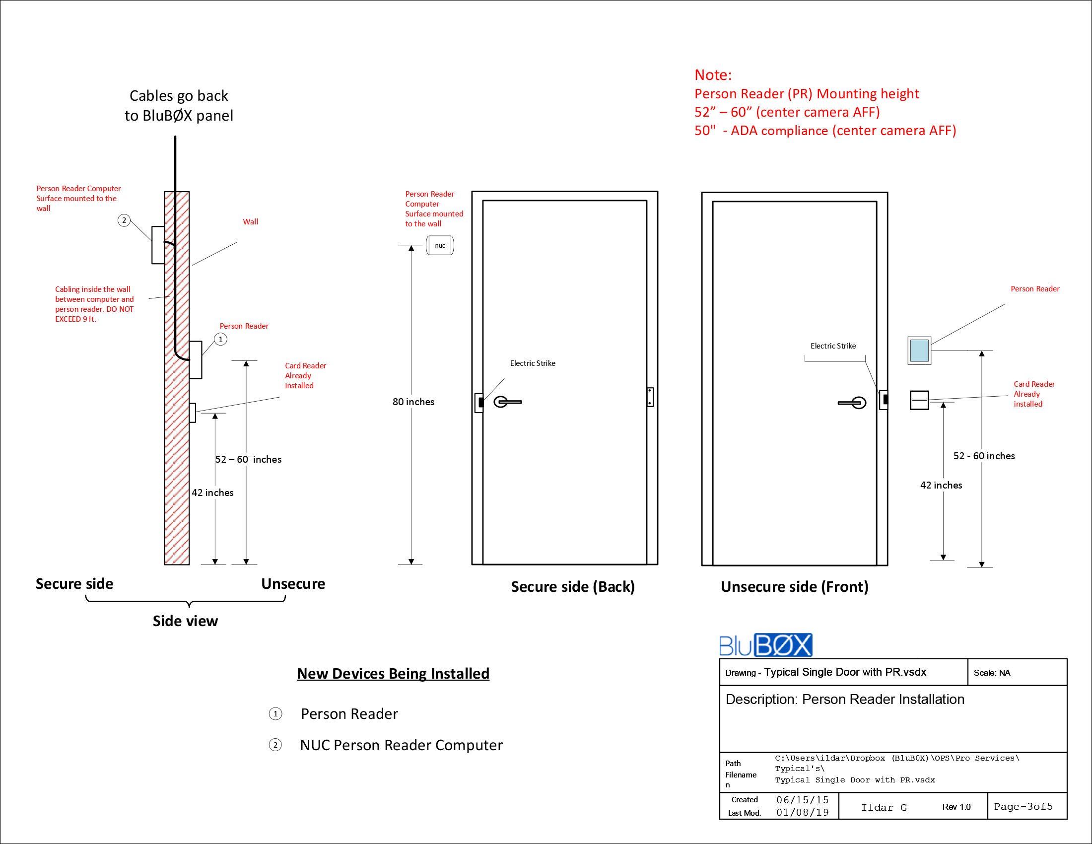
The selected Person Reader sensor head is mounted on the unsecured side of a secure portal. The sensor head is interconnected with its support hardware (NUC PC) via USB, HDMI, and Audio cables. These cables are run to the support hardware, normally on the secure side of the portal controlled by the Person Reader, and within a distance of 6’ due to USB performance limits. Ethernet and Power wires are run from the support hardware location to the ACP and switch locations.
(TR - Add Typical Drawing here)
This document is divided into three sections:
- Section 1 - Sensor Head Mounting Location
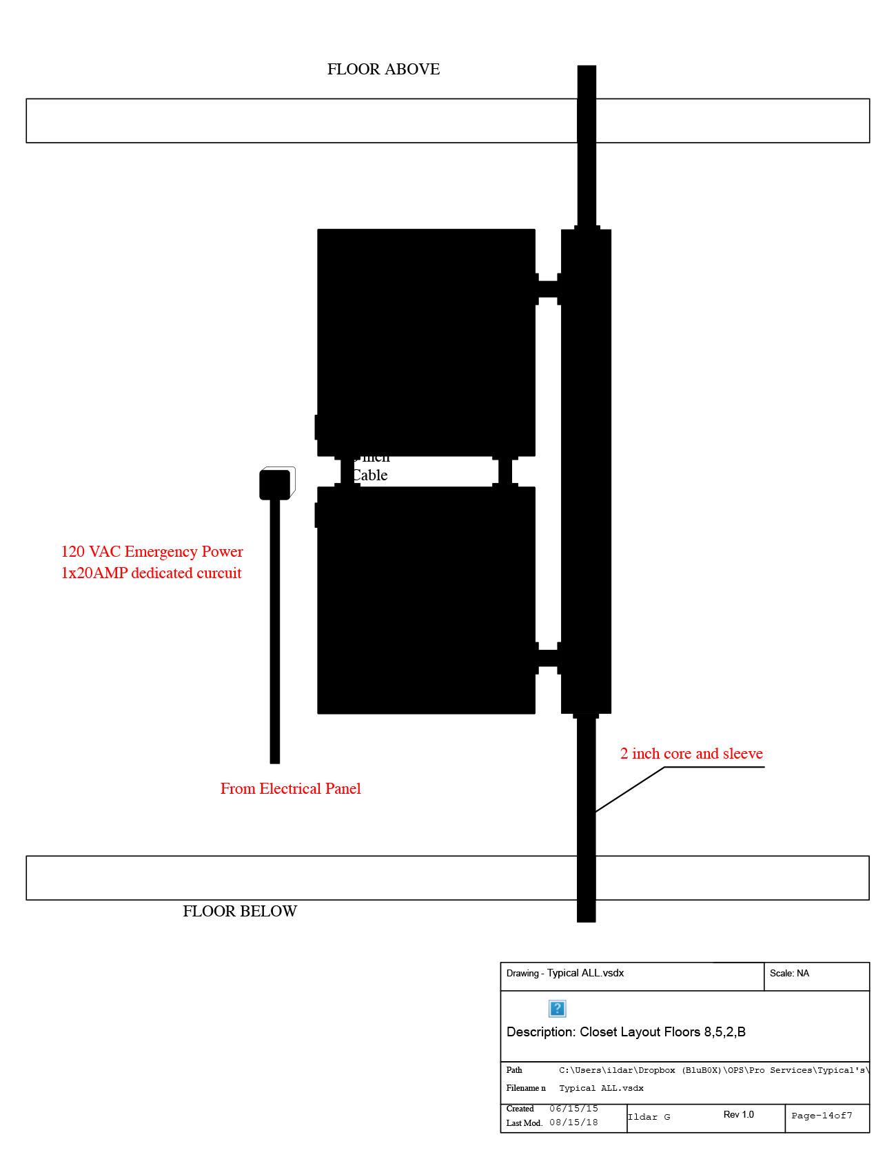
- Section 2 - Support Hardware Location
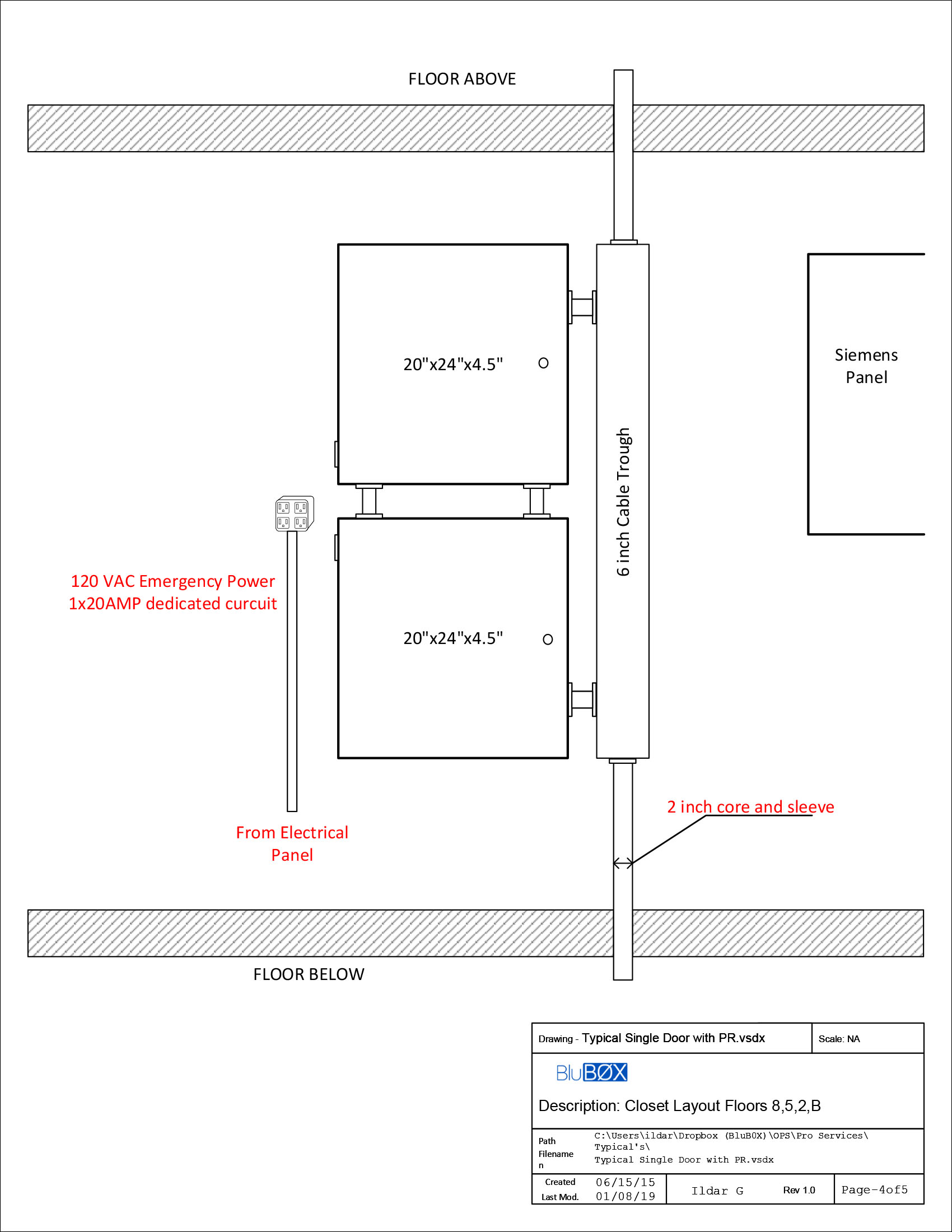
- Section 3 - Power and Access Control Panel interconnection.
Section 1 - Sensor Head Mounting Location
The sensor head is mounted next to a Portal to be secured, at a height of 52 to 60” above the finished floor. The sensor head should be installed to ensure the onboard camera is “looking” where an approaching portal user is walking. Example: The Sensor head can’t be installed too close to an adjacent wall without shimming the sensor head viewing angle back into the approach lane. Like any camera installation, lighting, back-lighting, and field of view must all be considered.
Mounting Requirements
-
Properly mounted readers should not alter the behavior of users approaching an unlocked door
-
Mount reader
-
Such that middle camera is 52” - 60” (center camera AFF)
-
ADA Compliance the PR can be mounted at 50" (center camera AFF)
-
Next to handle-side of the door
-
In the same plane as the door
-
Such that it is facing approaching users at an arm’s length
-
Away from spotlights

Things to Avoid
- Reader facing the door
- Obstructed field of view
- Hard or inconvenient for users to position themselves to face the PR

- Good placement
- Good lighting
- The reader recognizes you as you approach the door
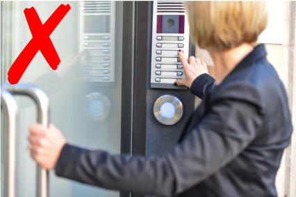
To frontally face this device users would have to:
- Block the door they are trying to open
- Face away from where they want to go
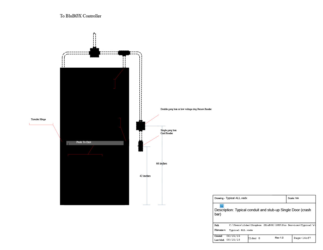
Typical - All
 |
 |
 |
 |
 |
 |
 |
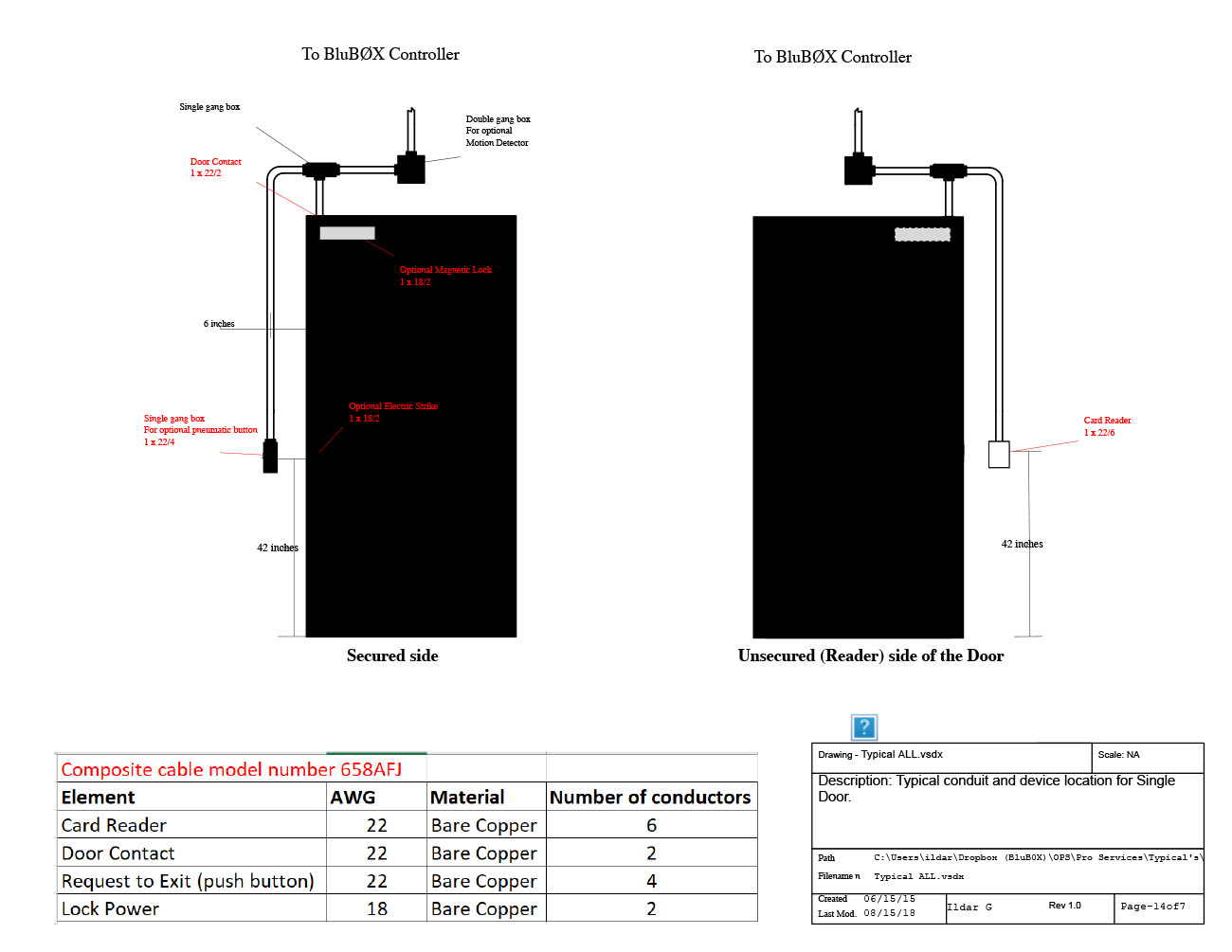
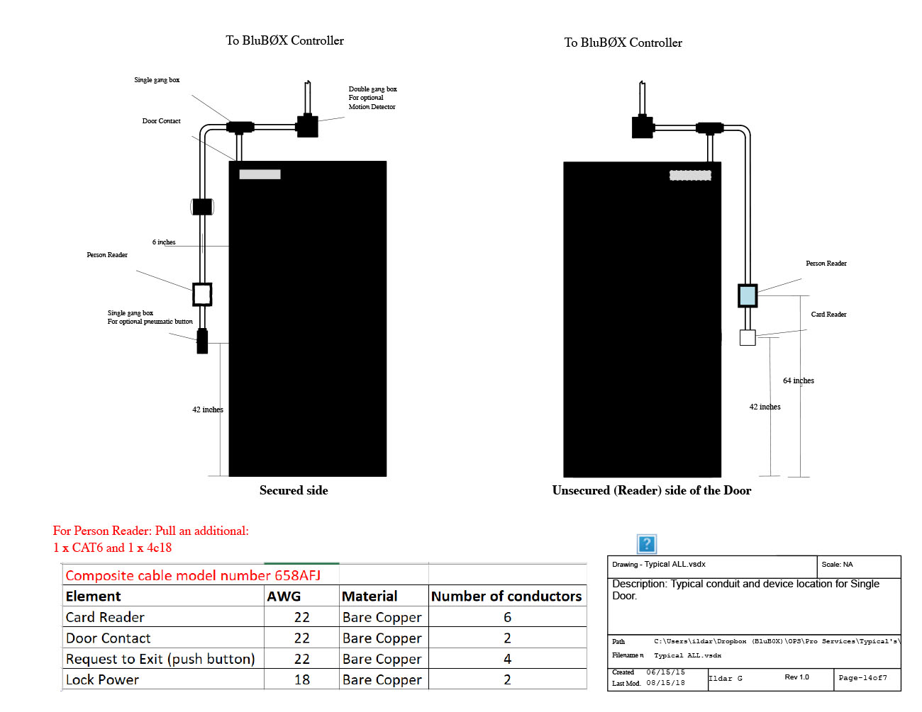
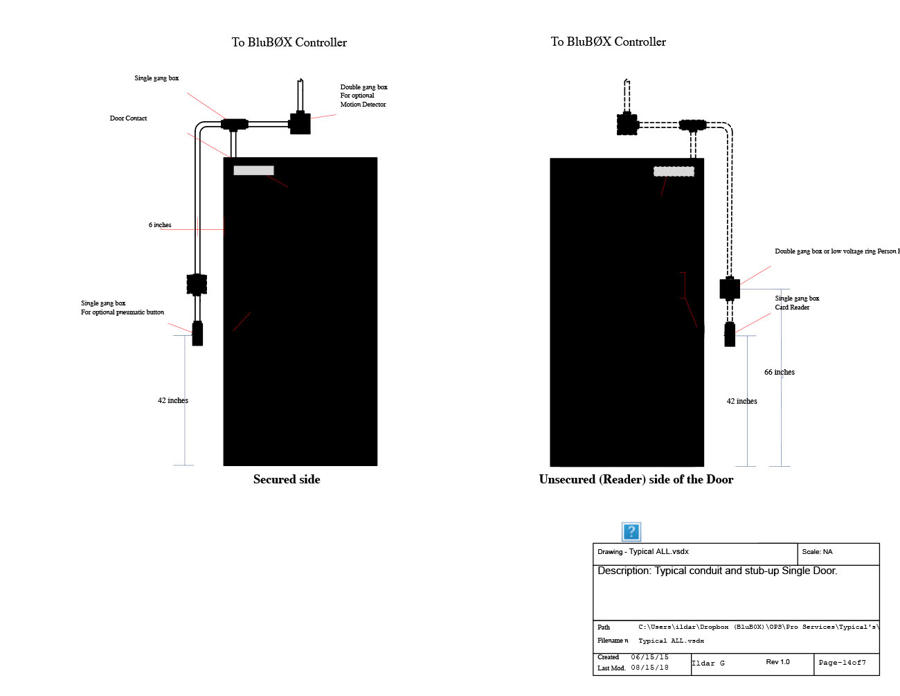
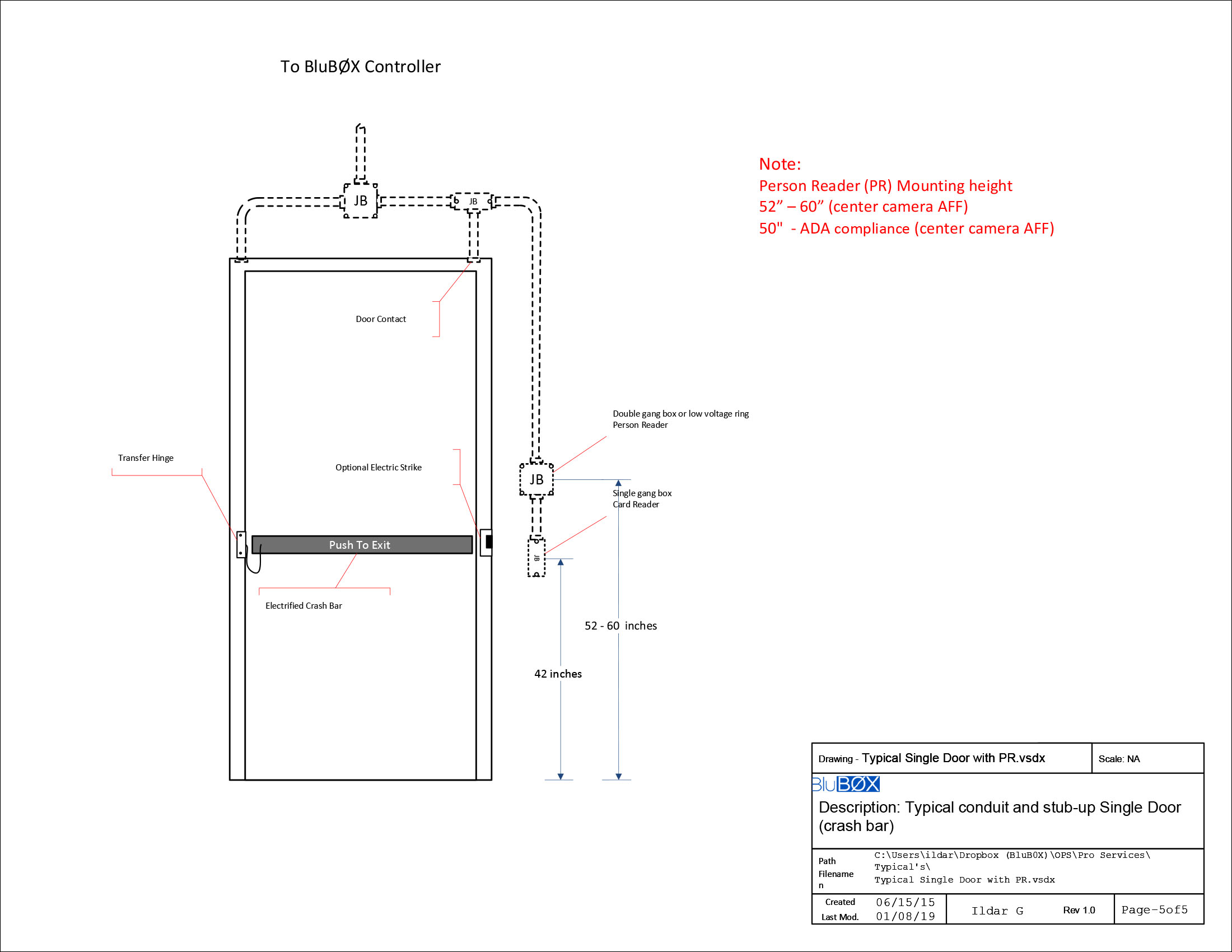
Typical Single Door with Person Reader
 |
 |
 |
 |
 |
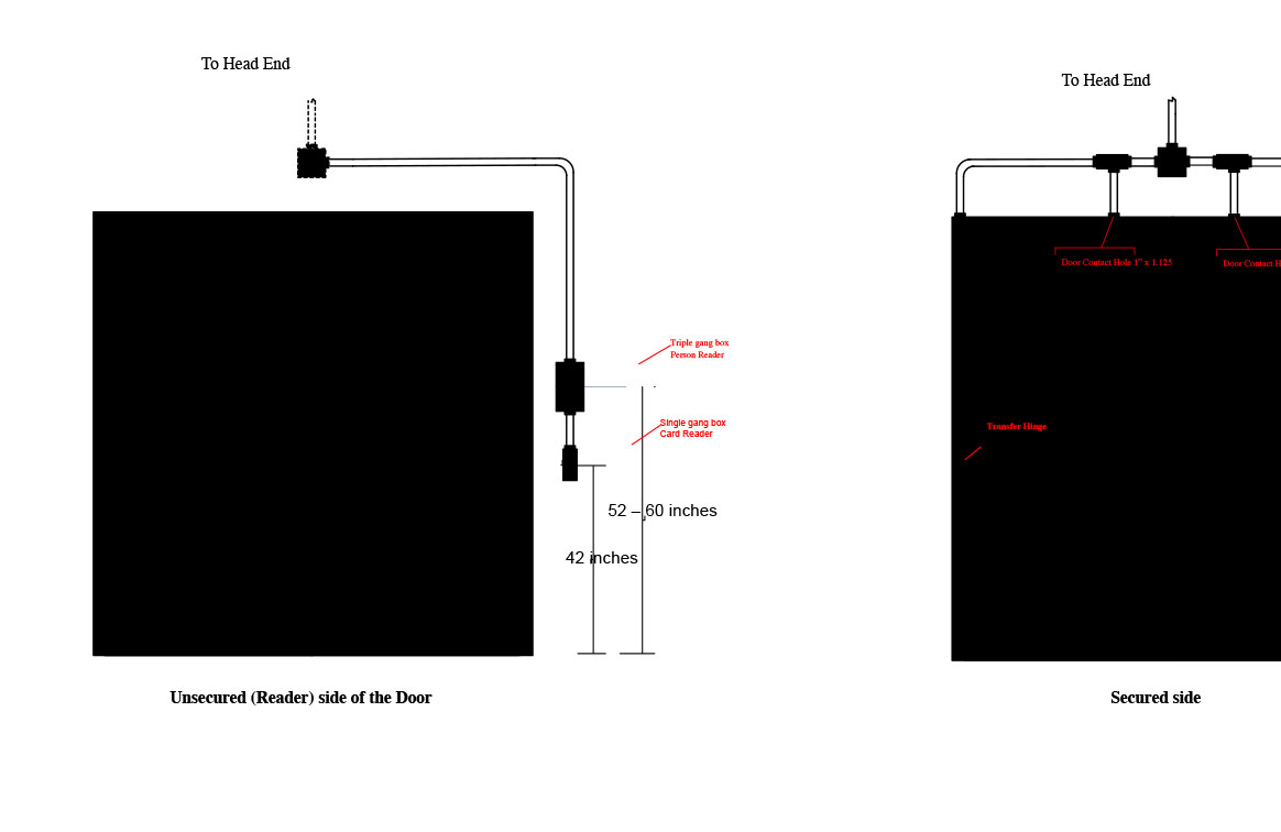
Typical Double Door with Person Reader
 |
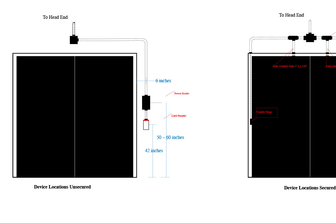
Device Location on Double Door
 |
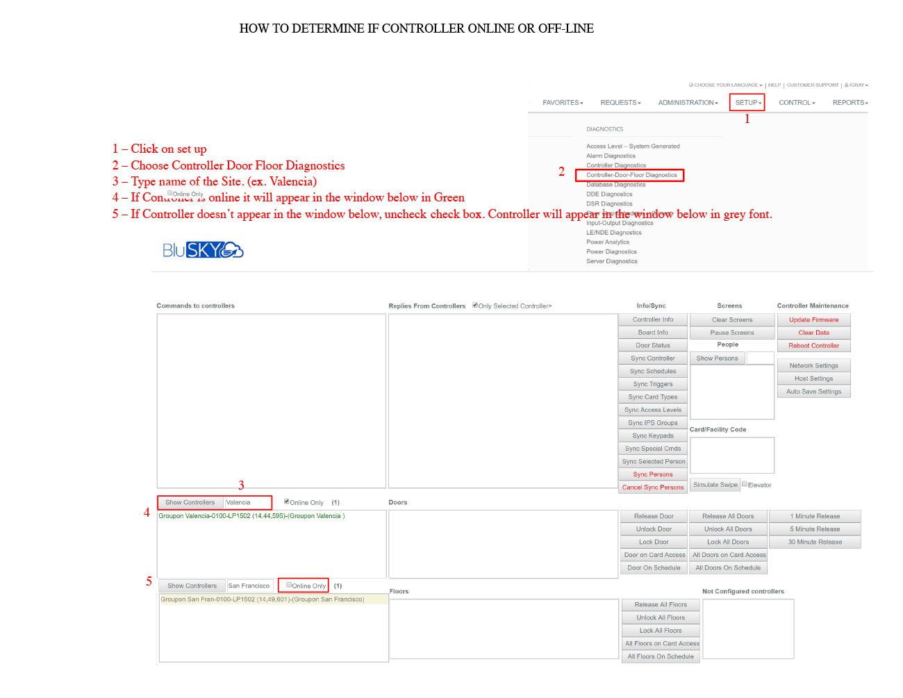
Panel Offline Troubleshooting Guide
 |
 |
Person Reader Wiring
Click to view wiring: PR Wiring.pdf

BluB0X Controller Main Components Description
| BB_Controller Main Components.jpg |